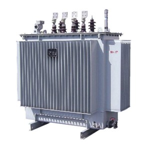
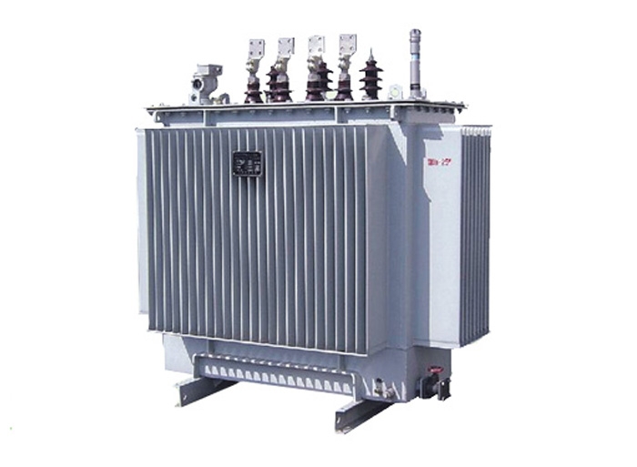
We will present the performance, safe operation methods, and technical parameters of 변압기: S 9 \ S 11 \ S 13 액체 채워진 변압기
This manual is applicable to fully sealed oil-iMmersed power transformers produced by our company, with a rated capacity of 3150KVA and below, and a voltage level of 35KV and below.
1. Uses and characteristics
일반 전력 변압기에 적합한 것 외에도 완전히 밀봉 된 오일 몰입 변압기는 특히 습도가 높고 유지 보수가 불편한 석유 화학, 야금, 섬유, 경공업 및 기업, 광산 및 농촌 지역에 적합합니다.
이 제품은 오일 저장 캐비닛 및 습기 흡수기와 같은 오일 보호 장치를 제거하여 변압기 오일이 공기와 접촉하지 않도록하며 모든 씰은 진공 오일 주입을 사용하여 우수한 특수 고무로 밀봉되어 정상적인 상황에서 변압기는 20 년 동안 처리없이 계속 사용할 수 있으며 유지 보수 비용이 낮습니다. 작동 신뢰성이 향상되고 서비스 수명이 연장됩니다.
2. Model description
S□-M-□ □
S - three phases
□ - Performance Level Code (11, 13, 20)
M – sealed
□ – Rated capacity (kVA)
□ – High Voltage Voltage Level (10kV)
3. Transportation
1.운송 및 설치 중에 변압기를 들어 올릴 때 연료 탱크의 4 개의 크레인을 동시에 사용하여 변압기의 최종 조립품이 변압기 오일로 채워진 후 변압기의 총 무게를 짊어져야합니다.이 요구 사항을 충족시킬 수 없는 경우 특수 빔 리프팅 변압기를 사용해야합니다.
2.이 제품의 고정부품은 모두 완화 너트로 안정적인 고정력을 보장합니다.그러나 운송 중에 변압기가 충분한 안정성을 가지고 있는지 확인해야하며 변압기의 경사는 15 ° 를 초과하지 않아야합니다.들어올릴 때는 부드럽게 들어올리고 풀어야하며, 들어올리기 장비가 없는 상태에서는 지면을 천천히 움직여 격렬한 진동을 방지해야합니다.
4. Acceptance and storage
1.변압기를 접수한 후 사용자는 즉시 명판에 따라 제품 모델 및 사양을 확인하여 사양이 주문 계약과 일치하는지 확인한 다음 변압기의 각 부품이 손상되었는지, 신호 온도계, 케이싱 등과 같은 취약한 부품이 손상되었는지, 신호 온도계 호스가 평평하고 깨졌는지 확인해야합니다.도자기 슬리브의 무결성에 특히주의를 기울여야하며, 케이싱에 오일 누출이 있는지 여부를 판단하고, 변압기의 각 밀봉 부분에서 오일 누출 또는 오일 누출이 있는지 확인해야합니다.
2. 변압기가 설치되지 않고 즉시 작동하여 장시간 보관해야하는 경우 모든 씰을 밀봉하고 예비 부품을 올바르게 보관해야하며 보관 상황을 정기적으로 점검해야합니다.
5. Installation and maintenance of transformers
1. Installation of transformers
1.1 The user uses a forklift or other handling tools to smoothly transport the transformer to the designated installation position.
1.2 Be careful not to damage the casing and other wearing parts during installation, and do not scratch the fuel tank or scratch the paint film.
2. Inspection and judgment criteria before the transformer is put into operation
2.1 After the fully sealed oil-iMmersed power transformer is transported to the user, there is no need to check the core.
2.2 The transformer should be tested according to the "Test Standard for the Handover of Electrical Equipment in Electrical Installation Engineering".
2.2.1 Measure the DC resistance of the winding and the sleeve, and the value should not be greater than 2% compared with the factory measured value at the same temperature.
2.2.2 Check the changes of all taps and there should be no significant difference compared with the factory data.
2.2.3 Check whether the coupling group designation of the transformer is consistent with the nameplate mark.
2.2.4 The insulation resistance value should be close to the factory value at the same temperature, and should not be less than the value in Table 1.
Table 1 Insulation resistance value (MΩ)
temperature
| 20 | 30 | 40 | 50 | 60 |
<6 | 400 | 200 | 100 | 50 | 25 |
6 or more but less than 20 | 800 | 400 | 200 | 100 | 50 |
20 or more than 60 | 1000 | 500 | 250 | 125 | 65 |
Description: 1. The coil under test is grounded during the measurement. 2. Use a 2500V megaohm meter or a special meter.
2.2.5 The external construction frequency withstand voltage test voltage of the winding and the casing is shown in Table 2.
Table 2 Experimental standards for insulation power frequency withstand voltage of high-voltage electrical equipment
정격 전압 (KV). | 3 | 6 | 10 | 15 | 20 | 35 |
Factory experimental value | 18 | 25 | 35 | 45 | 55 | 85 |
Handover experimental values | 15 | 21 | 30 | 38 | 47 | 72 |
2.2.6 The conventional test items of transformer oil are inspected according to the requirements of new oil (before putting into operation), see Table 3.
Table 3 Experimental items and standards of transformer oil before putting into operation
일련 번호 | 아이템들 | New oil in the tank before putting into operation |
1 | appearance | Transparent and free of impurities |
2 | Flash point C (sealed) | 140 |
3 | Moisture mg/1 (ppm). | ≤20 |
4 | Acid value mgKOH/g | <0.03 |
5 | Breakdown voltage KV (2.5Mm) oil gap | 35KV and below: ≥35 |
6 | The medium is lost tangentially tangents by 8% (90°C). | ≤0.7 |
7 | Interfacial tension mN/m (25°C). | ≥35 |
8 | Water-soluble acid (PH). | ≥5.4 |
2.2.7 Oil sample collection method
(1) Scrub and dry the glass test cup with a diameter of about 80-100Mm and the syringe barrel of about 100ml.
(2) Unscrew the oil sample valve cover at the bottom of the fuel tank.
(3) Wipe the oil sample valve outlet and vicinity clean with clean paper or cloth.
(4) Align the glass test cup with the valve outlet.
(5) 렌치를 사용하여 오일 샘플 밸브의 볼트를 천천히 풀어서 오일이 컵으로 흐르도록하고 동시에 주사기 바늘을 오일 샘플 밸브의 오일 배출구에 넣어 오일 샘플을 끌어냅니다.
(6) The amount of oil sample is determined by the user according to the needs of the experimental project.
(7) When the oil sample is collected, tighten the oil sample valve bolt and valve cover.
(8) 변압기 상자 덮개의 상단에있는 오일 분사 파이프 덮개를 열고 동일한 모델의 변압기 오일을 천천히 붓고 동일한 무게로 테스트를 오일 분사 파이프에 통과하고 오일 분사 파이프 커버를 조입니다. 오일 샘플 및 오일 보충 과정이 완료됩니다.
3. Maintenance of transformers
3.1 The maintenance and inspection standards of fully sealed oil-iMmersed transformers are as follows in Table 4 and Table 5.
Table 4 Regular inspection standards
일련 번호 | Inspection items | Inspection essentials | Cycle | Judgment criteria | remark |
1 | Insulation resistance | Use a 2500V rocking meter or a measuring instrument with the same effect Measure the phase to the ground | Irregular | 35KV side: 270MΩ 10KV side: 200M Ω 1KV side: 50MΩ | After a serious overvoltage or serious accident, this experiment is carried out |
2 | Insulating oil | Chromatographic analysis | 6 years | GB7252-87 "Guidelines for the Analysis and Judgment of Dissolved Gas in 변압기 Oil" | After a serious overvoltage or serious accident, this experiment is not limited by the period |
3 | thermometer | 1. Internal spot inspection (rust and moisture absorption) 2. Gask condition 3. Temperature indication, indicating action 4. Temperature rating | 2 years | 1. No rust 2. No damage 3. Indicate normal action (gently tap) 4.85°C | |
4 | Oil level gauge | 1. External inspection 2. Whether the oil surface is full of oil | 1 year | 1. No rust, no oil stains on the glass 2. Whether the oil surface line can be seen | There is no oil level gauge This item will not be inspected |
5 | casing | 1. Terminal status 2. Sleeve status 3. Does oil leak? | 2 years | 1. There is no loosening or discoloration 2. There is no damage or defacement 3. No oil leakage or air leakage | If there is any abnormality, it should be dealt with in time |
6 | Grounding wire | Rugged state | 2 years | No loosening, no broken wires | |
7 | pressure release valve | 1. Whether the seal is oily 2. Whether the lead wire connection is firm | 2 years | 1. No oil seepage 2. If there is any abnormality, it should be dealt with in time | If there is leakage Deal with it in a timely manner |
Table 5 Daily inspection standards
일련 번호 | Inspection items | Inspection essentials | Cycle | Judgment criteria | remark |
1 | Body appearance | There is no dirt, cracks or oil seepage | January | There should be no dirt, cracks, oil leakage, etc | If there is any abnormality, it should be dealt with in time |
2 | The sound and odor of the body | Abnormal sounds and smells (hearing, smell) | January | 1. Sounds and vibrations caused by excitation are normal 2. Abnormal sounds such as loosening and discharging of the fastening nut of the conductive part 3. The combustion of insulation will have a special odor | If there is any abnormality, investigate the cause and deal with it in a timely manner |
3 | Body temperature | Whether the temperature rise is normal | January | The load current borne by the transformer is related to the temperature rise of the oil surface | If there is any abnormality, investigate the cause and deal with it in a timely manner |
4 | Body oil surface | Whether the oil surface is normal (oil surface table) | January | The oil should be filled with an oil level gauge | If there is no oil level gauge, no spot inspection can be done |
5 | current | Whether the current exceeds the allowable value and whether the three-phase current is balanced (AMmeter) | January | The current of each phase is roughly balanced within the rated range | If the imbalance is serious, it should be adjusted in time |
3.2 Oil seepage treatment and oil replenishment method
3.2.1 If the oil seepage at the seal is leaked, the spiral can be tightened with a wrench and the oil stains can be wiped dry.
3.2.2 If the sealing material causes oil seepage, the seal should be replaced.
3.2.3 Oil seepage in the weld should be dealt with in time.
3.2.4 After oil seepage treatment, the oil replenishment method is the same as point 8 of 2.2.7.
3.2.4.1 오일 보충량: 정상적인 상황에서는 탱크에서 흘러 나오는 오일의 양이 적기 때문에 오일 보충량은 탱크 뚜껑에 오일을 채우고 그 당시의 오일 온도와 주변 온도는 무시할 수 있습니다.
3.3완전 밀봉된 변압기의 진공 오일 주입의 목적은 진공 조건에서 코일 내부의 가스를 가능한 한 제거하여 변압기 오일이 코일 및 절연재 내부의 틈을 채우고 변압기의 절연 성능 및 서비스 수명을 향상시키는 것입니다.오일 누출으로 인한 오일 보충량은 매우 적기 때문에 코일의 절대 전력에 영향을 주지 않습니다.
가장자리 성능 (제조업체는 진공 오일 주입 공정에서 규정합니다 : 진공 오일 주입 조건 하에서 오일 주입은 박스 덮개에서 약 100 Mm 떨어져서 오일 주입을 중단하지만 진공은 1 시간 동안 계속되고 오일 주입 파이프에서 오일 주입 파이프에서 오일 레벨이 오일 주입 파이프의 상단까지 상승하도록합니다).
6. Permitted operation mode
1. Rated operation mode
1.1 The transformer should be equipped with a temperature protection relay, which can be operated according to the nameplate specifications under the specified cooling conditions.
1.2변압기의 작동 중 허용 온도는 상단 오일 온도 상승에 따라 확인되며 상단 오일 온도 상승의 허용 값은 55 °C 이지만 최대 온도는 95 °C 를 초과하지 않아야합니다.변압기 오일의 급속한 노화를 방지하기 위해, 상단 오일 온도는 종종 85 ° C 를 초과해서는 안됩니다.
1.3스텝 업 변압기 및 스텝 다운 변압기의 적용 전압은 정격 값보다 높을 수 있지만 일반적으로 정격 값의 5 % 를 초과하지 않으며 전압 탭이 어디에 있든 1 차 전압이 적용되면 해당 전압 값의 5 % 를 초과하지 않으며 변압기의 2 차 측면은 정격 전류를 가질 수 있습니다.
2. Allowable overload
2.1변압기는 정상 과부하와 사고 과부하에서 작동할 수 있습니다.정상 과부하를 정기적으로 사용할 수 있으며, 허용 값은 변압기의 하중 곡선, 냉각 매체의 온도 중심 및 과부하 전의 변압기의 하중에 따라 결정됩니다.사고 과부하는 사고 상황에서만 사용할 수 있습니다.예를 들어, 작동 중인 여러 변압기 중 하나가 손상되어 백업 변압기가 없으면 나머지 변압기는 사고 과부하에 따라 작동하도록 허용됩니다.
2.2 The allowable value of transformer accident overload shall be specified in the following table:
| The ratio of accident overload to rated load | 1.3 | 1.5 | 1.75 | 2.0 | 3.0 |
Allowable duration of overload (minutes) | 120 | 45 | 20 | 10 | 1.5 |
3. Unbalanced current of the allowable short-circuit current.
3.1 The short-circuit current of the transformer shall not exceed 25 times the rated current, and the short-circuit current passage time shall not exceed the value calculated according to the following formula:
T=900/K seconds, where K is a multiple of the stable short-circuit current to the rated current.
3.2 For transformers whose coils are connected according to Y, yn0, the midline current shall generally not exceed 25% of the rated current of the low-voltage coil (except for special requirements from users)
Instruction manual for general components of oil-iMmersed power transformers
1. Overview
이 사용 설명서는 케이싱, 탭 체인저, 압력 방출 밸브, 오일 샘플 플랩, 온도계 시트, 접지 볼트 및 오일 드레인 밸브를 포함하여 공장에서 생산 된 전력 변압기의 일반적인 구성 요소에 적합합니다. 다른 표준 구성 요소에는 사용 설명서가 수반됩니다.
2. Use and maintenance
(1) Instruction manual for transformer bushings of 35 kilovolts and below
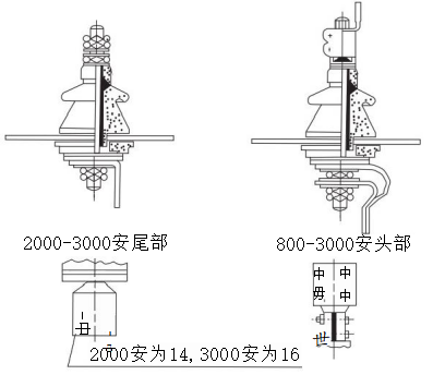
그림 1
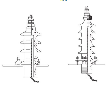
Figure 2 그림 3
1. 그림 1 은 1 천 볼트의 전압에 사용되는 복합 케이싱이며, 전류는 300-3000A 입니다. 그림 2 는 10 천 볼트의 전압에 사용되는 케이블 유형 슬리브, 전류는 50-300A 입니다. 도 3 은 35 kV 의 전압과 35-600A 의 전류를 갖는 나사 슬리브를 나타낸다.
2. When the transformer leaves the factory, the casing is assembled on the transformer oil tank and sent to the user together with the transformer.
3. If you need to disassemble or replace the porcelain type, it should be carried out in the following way.
(1) 복합 케이싱, 먼저 리프팅 바디를 들어 올린 다음 케이싱의 하부의 리드를 제거한 다음 마지막으로 모든 고정 너트를 풀고 케이싱을 제거하고 스크럽 및 건조 된 교체 케이싱을 교체하십시오.
(2) 케이블 형 케이싱의 경우 케이싱을 교체 할 때 케이싱을 외부에서 교체 할 수 있으며 교체 할 때 조인트 너트를 풀고 조인트를 구리선 또는 사 벨트로 당겨 오일 탱크로 미끄러지지 않도록해야합니다. 밀봉 개스킷 및 압력 플레이트 등
4. When installing the casing on the transformer fuel tank, the following matters should be noted:
(1) 복합 케이싱의 경우 오일 누출을 방지하기 위해 변압기의 박스 커버에 도자기 부품을 완전히 고정하려면 케이싱의 상부와 하부를 조여 도자기 부품의 너트를 고정해야합니다.
(2) For the cable type casing, the nut of the presser screw that fixes the casing must be tightened evenly, and then the conductive rod is fixed after the casing is firmly installed on the transformer oil tank.
5. In perennial use, the casing should be scrubbed frequently according to the dirt situation to prevent the surface of the porcelain sleeve from being discharged.
(2) No excitation tap-changer
우리 회사에서 생산 한 3 상 오일 몰입 완전 밀봉 된 전력 변압기는 일반적으로 상자 덮개에 WSP 형 무부하 탭 체인저를 장착하여 전기가 없을 때 고전압 측면 탭 체인저를 변경합니다.
1. The typical structure of WSPII1 type non-excitation neutral point voltage regulator tap-changer is shown in Figure 4.
2. ± 5% 전압 조절 범위에서 탭 체인저 다이얼의 디지털 표시로 표시되는 전압 값의 경우: 1 은 정격 전압 값의 5% 를 갖는 탭 커넥터를 나타내고, 2 는 정격 전압 값을 나타내고, 3 은 정격 전압 값의-5% 를 갖는 탭 커넥터를 나타냅니다.
3.탭 체인저의 위치를 변경할 때, 항목 4 의 덮개에있는 나사를 풀고 제거해야하며, 항목 3 의 핸들 위치 부분을 그루브 구멍에서 끌어낸 다음 항목 2 를 필요한 탭 위치로 회전하고 핸들 위치 부분을 해당 그루브 구멍에 내장하고 커버로 덮어야합니다.
4.변압기의 요구로 인해 탭 - 체인저가 종종 한 위치에서 작동하는 경우, 접촉 부분의 산화물 필름과 오일 얼룩을 제거하고 좋은 접촉을 보장하기 위해 변압기가 전압을 변경해야하는지 여부에 관계없이 탭 - 체인저는 일년에 적어도 10 번 회전해야합니다.전압을 변경할 필요가 없는 경우 회전 후 원래 위치로 고정되며 탭 위치를 변경하고 브리지 또는 멀티 미터를 사용하여 작동하기 전에 경로를 측정해야합니다.
5.변압기 오일이 탭 변경기에서 누출되는 것을 발견하면 어디서 누출되는지 확인하십시오.변압기 연료탱크 덮개 및 탭체인저 플랜지에서 기름이 누출되면 항목 6 의 평면 너트를 즉시 조이고, 샤프트 및 플랜지에서 기름이 누출되면 항목 5 의 너트를 조여야 하지만 회전 토크의 과도한 증가를 방지하기 위해 너무 단단히 조이지 않아야 합니다.
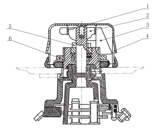
Figure 4 WSPIII Type 1 tap-changer
중간 전압 조절이면 WPS II.1 비 여기 탭 체인저가 사용되며 작동 및 유지 보수 방법은 기본적으로 위와 동일합니다. 위 이외의 비 여기 탭 체인저에 대해서는 해당 탭 체인저 매뉴얼을 참조하십시오.
(3) Pressure release valve
1. 제품 Usage and Performance Introduction:
압력 방출 밸브 (이하 방출 밸브라고 함) 는 연료 탱크를 보호하기 위해 액체 또는 가스 절연 변압기, 변압기, 온-로드 탭-체인저, 고전압 스위치, 커패시터 및 기타 제품에 적합합니다.
변압기 내부 또는 온로드 탭 변경기 내부에서 사고가 발생하면 변압기의 일부가 가스화되어 변압기 탱크 내부의 압력이 빠르게 증가합니다.신뢰할 수 있는 보호를 받지 않으면 탱크가 변형되거나 심지어 파열될 수 있습니다.릴리프 밸브는 변압기 탱크가 손상되지 않도록 보호합니다.연료 탱크의 압력이 릴리프 밸브의 작동 압력에 도달하면 릴리프 밸브가 2 밀리초 이내에 열리고 연료 탱크의 과압을 제 시간에 풀어줍니다.
릴리프 밸브가 열리면 연료 탱크의 압력이 작동 압력의 약 53 - 55% 로 떨어지고 릴리프 밸브가 안정적으로 닫힐 수 있습니다.이 릴리프 밸브의 특수 기능은 보호 대상의 특수 요구 사항이며 연료 탱크를 손상으로부터 효과적으로 보호 할 수 있습니다.탱크의 압력이 다시 상승하여 작동 압력에 도달하면 탱크의 압력이 정상 값으로 떨어질 때까지 릴리즈 밸브가 다시 작동합니다.변압기의 전원이 켜지면 11 번째 안전 장치를 제거해야 합니다.
Because the release valve can be reliably closed after action, the air and water outside the fuel tank cannot enter the fuel tank, and the transformer oil will not be polluted by the atmosphere.
2. Model, specifications, and basic parameters
2.1 model
YSF□-□ □ □
YSF – Pressure Relief Valve Code
□ - 디자인 일련 번호
□ – Turn on the pressure kPa
□ - the effective caliber of the oil injection Mm
□ - Alarm signal environmental conditions and locking device*
※: 1. Used for mechanical signal mark "J".
2. For use in humid tropical areas, add "TH" after the "J" mark.
3. If a locking device is used, then add "B" after it.
For example: YSF6-35/25JTHB
That is, the oil injection diameter φ25Mm, the opening pressure is 35kPa, with a mechanical alarm signal, it is used for the damp and hot zone locking device, and the sixth design of the pressure release valve.
2.1 Specifications and basic parameters are shown in Table 1
3. The structure of the structural pressure release valve is shown in Figure 5.
Table 1 Specifications and basic parameters
Effective caliber (Mm) | Turn on the pressure (kPa) | Open pressure limit deviation (kPa). | Turn off the pressure (kPa) | Sealing pressure (kPa) |
φ25 φ50 | 15 | ±5 | 8 | 9 |
25 | 13.5 | 15 | ||
35 | 19 | 21 | ||
55 | 29.5 | 33 |
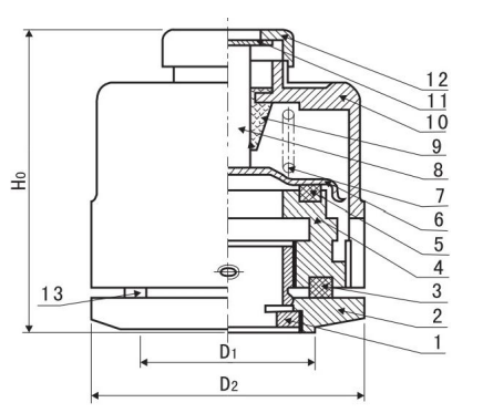
Fig.5 Schematic diagram of the structure of the pressure release valve
4. Use
Choose a release valve equipment with a latching device, and the latching pin should be removed before the equipment is put into operation, otherwise the valve cannot be opened.
After the operation of the pressure release valve during operation, the marker rod should be reset after the fault is found for reuse. The release valve cannot be removed at will during installation.
The pressure release valve has oil leakage, and measures should be taken to solve it in time, and the main reasons for oil leakage are roughly as follows:
a. For some reason, the pressure in the fuel tank is too high, which has exceeded the sealing pressure of the release valve but has not yet reached the opening pressure, causing leakage.
b. Some of the sealing rings in the valve have been aged and failed, and the failed sealant ring should be replaced with the manufacturer in time.
c. If there is a foreign object on the sealing surface, it can be eliminated in time.
5. Maintenance and overhaul
5.1 Take advantage of the opportunity of each power outage maintenance of electrical equipment to carry out the following maintenance of the valve.
a. Whether the opening action is sensitive.
B. 밀봉 링이 노화, 변형 또는 손상되었는지 여부. 이상이 발견되면 고무 링의 노화로 인한 오일 누출 또는 방출 밸브의 고장을 피하기 위해 제 시간에 교체해야합니다.
c. Clear the foreign body in the valve.
d. Whether the parts are rusted, deformed or damaged.
5.2 The user should prepare several release valves in case of replacement during inspection.
(4) Oil sample flap
일반적으로 오일 샘플 용 연료 탱크 하부의 저압측 방향으로 설치됩니다. 사용할 때 먼저 덮개를 풀고 부드러운 조인트 1 에 오일 샘플 호스를 넣은 다음 커넥터에서 오일이 방출 될 때까지 플러그를 천천히 비틀고 완료 후 덮개를 조입니다.
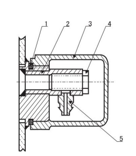
Figure 6
(5) Thermometer seat
변압기의 오일 표면의 온도 상승을 측정합니다.측정용 수은 온도계는 사용자가 제공합니다.온도계 시트의 구조는 그림 7 에 표시되어 있습니다.온도 센서 소켓에는 변압기 오일이 채워져 있으며 오일 표면 온도 상승을 측정하면 덮개를 열고 수은 온도계를 삽입하십시오.측정 후 온도계를 꺼내서 덮개를 다시 단단히 꽉 눌러주세요.
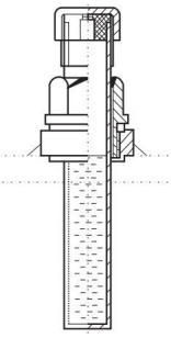
Figure 7
(6) Grounding bolts
접지 볼트는 변압기의 전체 접지를 위해 탱크의 저전압 측면의 하단에 용접됩니다.그 구조는 그림 8 에 표시되어 있다.항목 2 와셔에서는 가정용 연결이 접지 버스바에 연결되어 있으며 항목 3 의 볼트를 조임하여 변압기의 안전한 작동을 보장합니다.쉽게 식별할 수 있도록 접지 표지판이 있습니다.
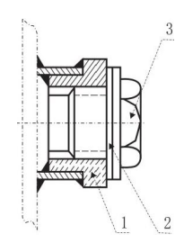
Figure 8
(7) Oil flap
The oil drain valve is installed in the direction of the low voltage side of the fuel tank for transformer accidents or for cleaning and draining oil.
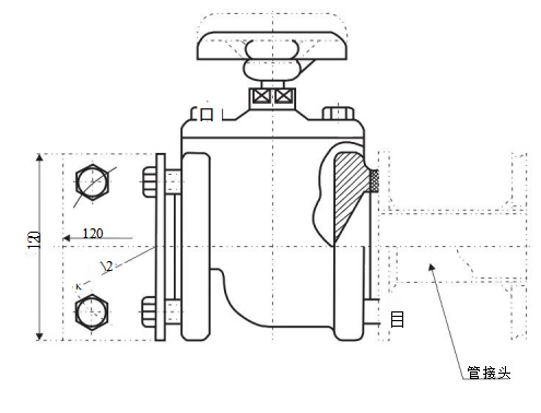
Figure 9
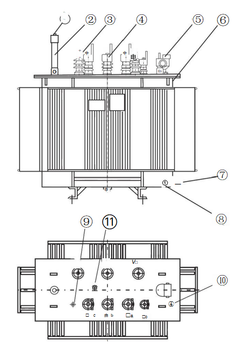
Fully sealed oil-iMmersed power transformer component
일련 번호 | Code | Name | quantity | Remarks |
11 | tap-changers | 1 | ||
10 | Signal thermometer mount | 1 | There are more than 1000KVA | |
9 | Mercury thermometer holder | 1 | ||
8 | Ground bolt | 1 | ||
7 | Oil sample flap | 1 | ||
6 | 변압기 cabinet | 1 | ||
5 | Gas relays | 1 | There are more than 800KVA | |
4 | Low pressure casing | 4 | ||
3 | High pressure casing | 3 | ||
2 | Oil level gauge | 1 | ||
1 | Pressure relief valve | 1 |
우리는 변압기의 성능, 안전한 작동 방법 및 기술적 인 매개 변수를 제시 할 것입니다: S9 \ S11 \ S13 액체 채워진 변압기