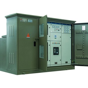
We will present the performance, safe operation methods, and technical parameters of ZGS - 12 패드 마운트 변압기
1. General provisions
이 설명서는 엔지니어와 기술자가 결합 된 변압기 (이하 조합기라고 함) 의 설치, 사용 및 작동을 지원하는 데 사용됩니다.
우리 공장에서 생산 된 결합 된 변압기는 벤치탑 설치를위한 완전히 절연 된 완전히 밀봉 된 방수 3 상 분배 변압기로 적합합니다. the three-phase distribution system with a rated voltage of 10KV. Meet the requirements of the corresponding national standards
이 설명서는 전기 장비의 일반적인 작동 절차를위한 서브 시니 움이 아니며 설치, 사용 및 작동의 모든 요구 사항을 충족시킬 수 없습니다.. These tasks should be carried out with personnel familiar with the safety and operating procedures of the power system
2. Use conditions and environment
a. Altitude: no more than 1000M.
b. Ambient temperature: -25C to 40C
c. Relative humidity: not more than 95% (daily average).
d. Ground inclination: no exercise 3.
e. Wind speed: no more than 35m/s.
Indoor and outdoor places without violent shock and vibration, no serious pollution and chemical corrosion media, and no explosion hazard.
3. Main technical parameters
일련 번호 | 이름 | 단위 | High pressure side | 변압기 | 낮은 압력 측면 |
1 | 정격 전압 | KV | 10 | 0.4 | |
2 | 최대 작동 전압 | KV | 12 | ||
3 | 정격 용량 | KVA | 50-2500 | ||
4 | 정격 현재 | A | 10-630 | 100-2500 | |
5 | Withstand current for a short time | KA | 12.5/20 | 12.6-40 | |
6 | Short tolerance time | S | 2 | 1 | |
7 | Peak withstand current | KA | 50 | 30-60 | |
8 | 전원 주파수 압력 저항 | KV | 35 | 35 | 5 |
9 | Lightning impact withstand pressure | KV | 75 | 75 | |
10 | High-voltage current-limiting fuses quickly cut off the current | KA | 50 | ||
11 | 보호 수준 | Ip33 | Ip65 | Ip33 | |
12 | 노이즈 레벨 | db | W55 | ||
13 | 정격 주파수 | Hz | 50/60 |
4. Unpacking acceptance inspection
제품의 손상, 변형 및 파손이 있는지 확인하십시오. 포장 목록에 따라 액세서리 및 특수 도구가 완전한지 확인하십시오. install according to the installation requirements after confirming that they are correct.
5. Installation
A. A어셈블리는 어셈블리의 무게를 감당하기에 충분한 100 - 400 mm 의 높이를 가진 콘크리트 기초에 설치됩니다.조립품 크기와 베이스에 대한 권장 크기 다이어그램은 부록 1 에 나와 있습니다.
B. B.. The cable is placed before the group is in place and must be without electricity.
C.상자의 상단 근처에 적재 및 하역을위한 후크가 있으며, 리프팅 강철 케이블과 수직 선 사이의 각도는 스트레칭 시 30 을 초과 할 수 없습니다.필요한 경우 구조물 또는 리프팅 후크의 변형을 방지하기 위해 횡단보를 사용하여 강철 케이블을 지원해야 합니다.어셈블리 변압기의 무게의 대부분은 철 코어, 와이딩 및 절연 오일이있는 메인 박스에 집중되어 있으며 대부분의 고전압 및 저전압 터미널 박스는 비어 있으며 무게는 상대적으로 가볍습니다. (후크 또는 크레인의 부적절한 사용으로 인해 조립품 또는 기타 액세서리가 손상되거나 직원이 부상을 입을 수 있습니다.))
주의 사항: 그룹 변압기를 크레인으로 들어 올릴 수없는 경우 스케이트 보드 또는 롤러로 미끄러질 수 있습니다. 상자를 지지하고 삽입할 때 아래 롤러는 적어도 두 개의 잭이 필요하며 인접한 두 각도는 상자 바닥의 변형을 피하기 위해 동시에 부드럽게 들어 올려야합니다. 잭 상자 바닥의 모서리에만 놓을 수 있으며 뒷판을 추가해야하며 잭은 방열판, 밸브 또는 얇은 강철 아래에 놓아서는 안됩니다. 접시. 롤러를 사용하는 경우, 수는 적절해야하며 상자의 무게는 동일하게 운반되어야합니다. 변압기를 당기기 전에, 상자 변압기의 바닥 양쪽에 당김 링을 설치하십시오. 재그룹화 된 주조 또는 기타 판금 부품에 케이블을 부착하지 마십시오.
D.. Installation site
조성물에 두 가지 유형의 절연유가 있으며, 하나는 높은 점화점 오일이고 다른 하나는 고품질 미네랄 오일입니다.높은 점화 오일을 가진 그룹 트랜스포머 (표시 표시가있는) 그룹 변압기의 저전압 격리 실) 은 건물 또는 실외에서 사용할 수 있습니다. 미네랄 오일의 조성은 buildings. The freezing point of high-quality mineral oil is -45.다음으로; 고성화 오일의 동결점은 - 30 입니다. 1.높은 점화 오일의 조합은 주변 온도가 - 30 ° C 보다 낮은 지역에서는 사용할 수 없습니다.고품질 미네랄 오일 또는 고성화 오일의 조합이든, 주변 온도가 - 20 ° C 보다 낮을 때 가동되면 예열을 위해 부하없이 24 시간 동안 작동해야하며 점차적으로 로드해야합니다.의심이있는 경우, 우리 공장에 연락하십시오.
6. Handover test
설치가 완료되면 테스트 케이블 플러그 (테스트 케이블 플러그를 옵션으로 구입할 수 있음) 를 연결하고 국가 표준의 관련 테스트 절차에 따라 인수 테스트를 수행합니다..
7. Installation precautions
A. When accessing the system
B. B.efore wiring any system, ground the box first. The grounding terminal of the box must be connected to a fixed, low-impedance grounding point.
B. B.efore wiring, clean all sleeves, bushings, terminal terminals and contacts, and clean all dust, oil and foreign objects. Connecting the neutral point of the group change and the neutral point of the system.
Install accessories as required to ensure the insulating oil is at the appropriate height.
When no one is on duty, close and lock the box door.
8. When operating
☆ 정상적인 상황에서 퓨즈를 삽입하는 작업은 전원이 차단된 후에 수행되어야하며, 작동하기 전에 관련 작동 지침을주의 깊게 읽으십시오.
☆ The internal load switch can only be used to interrupt the rated current, but not to disconnect the fault current.
☆ Insulated operating lever must be used to operate the load switch.
C. When maintenance is required
☆ 시스템이 작동하는 동안 그룹 변압기를 점검 할 수 없습니다. 유지 보수 전에 절연되고 전원이 꺼지고 그룹 변압기에서 완전히 격리되어야합니다.
☆ 플러그인 퓨즈를 작동시키고 오일 주입 밸브를 열고 변압기의 내부 압력을 풀고 (압력 릴리프 밸브를 꺼내기) 오일 탱크를 열기 전에 내부 압력이 0 이 될 때까지 위의 작업을 수행하지 마십시오.
Warning: The released gas may be flammable, so be careful when releasing it.
D.o not open the lid of the box of the group 변압기 unless it is absolutely necessary. B. B.efore opening, clean the area around the lid and close it in the shortest possible time to prevent moisture and dust from entering the box. D.o not turn on the group change in wet or rainy weather.
8. Operation
A. Inspection before commissioning
☆ Check whether the cable joints are connected as required, and whether the casing joints and elbow plugs are connected in place;
☆ All cable joints and the grounding wire of the box must be connected to a stable, low-impedance grounding point;
☆ After confirming that there is no problem, it can be put into operation;
☆ 그룹 변압기를 가동시키기 전에, 상자의 오일 레벨 높이를 확인해야하며, 오일 레벨 높이는 오일 레벨 게이지에서 직접 읽어야하며, 오일 레벨은 25 ° C 에서 25 ° C 에서 오일 레벨 게이지의 표시된 위치에 있어야합니다.
Note: 그룹 변경을 실행하기 전에 그룹 변경에 대한 자세한 내용을 파악해야 합니다.모든 장비 및 액세서리의 응용 프로그램 및 기능에 대해 잘 알고 있는지 확인하십시오.작업 중에 보호복과 필요한 보호 장비를 착용하고 장비를 접지, 테스트, 격리 또는 닫을 때 절연 된 작동 레버를 사용하십시오.재그룹 상태를 확인할 수 없는 경우 라이브 처리로 처리됩니다.
B. B.. Preparation for commissioning
a. Refill oil
When needed, oil should be replenished in a timely manner
☆ 오염되지 않은 펌프와 호스를 사용하십시오. 고무 호스를 사용하지 마십시오. 오일이 포함 된 황을 녹이기 때문에 금속 또는 비 고무 호스를 사용해야합니다.
☆ Connect the oil outlet pipe of the oil pump to the oil injection port of the oil tank.
☆ Pump the oil back from the bottom of the sealed temporary container, taking care not to let the oil inlet pipe draw in air.
☆ To prevent high-speed oil flow inflation, pump slowly until the oil level is required.
b. Grounding
The dedicated ground on the 변압기 enclosure must be connected to a permanent grounding point.
c. High-voltage wiring
☆ 조립품은 보편적 인 고전압 케이스 소켓을 장착합니다.케이스 소켓과 일치하는 단일 패스 또는 이중 패스 슬리브는 현장에 플러그해야합니다.단일 패스 및 이중 패스 슬리브의 설치 방법은 부록 3 에 표시되어 있습니다.
☆ 부록 4 에 설명된 설치 방법에 따라 고전압 배선 케이블에 토글 케이블 플러그를 장착한 다음 단일 또는 이중 패스 슬리브에 토글 케이블 플러그를 삽입합니다.
d. Low voltage wiring
There are three-phase and neutral wire terminals on the assembly 변압기 for connecting low-voltage cables.
Notice: 그룹은 명판에 지정된 등급에서만 작동 할 수 있으며 장기간 과부하 작동하면 기대 수명에 상당한 영향을 미칩니다.그룹이 너무 오랫동안 야외에 보관되면 오일 샘플을 채취하여 수분 함량과 절연 강도를 확인해야합니다.그룹이 공장을 떠날 때, 일반적으로 박스의 오일 표면 위에 낮은 진공이 있습니다 (압력 게이지가 음압을 표시), 정상적인 상황에서 작동 또는 환경의 변경으로 변경 될 수 있습니다, 압력 게이지가 오랜 시간 동안 0 압력을 표시하면 누출이있을 수 있음을 나타냅니다, 추가 검사가 필요합니다.
C. Operational requirements
☆ 작동하기 전에 라인의 작동 상태와 탭 - 체인저의 위치를 이해해야하며, 로드 스위치는 변압기와 연결이 끊어진 위치에 있어야합니다.
☆ Understand the purpose and function of all cable glands before operation;
☆ The operator should stand in the best position and use the insulated operating lever to operate the load before the operation.
☆ According to the relevant high-pressure operating regulations, necessary protective equipment must be used to ensure safety.
D.. Power transmission
Close the previous level switch, and then turn 8. 3 의 요구 사항에 따라 변압기를 연결하는 위치로로드 스위치가 이루어지며 그룹 변압기가 작동합니다.
9. Attachments
A. Tap changer
☆ 그룹 변수 탭 체인저는 무부하 탭 체인저이며, 탭 체인저는 전원이 차단되었음을 확인할 때만 수행 할 수 있습니다.
☆ The tap-changer has three or five gears, marked by A, B. B., C, D., and E, and the tap-out range is 10KV±5% or 10KV±2*2. 5%。
☆ 탭 - 체인저의 "T" 모양의 작동 핸들은 고압 챔버의 패널에 설치되며, 작동하기 전에 잠금 볼트를 풀고 필요한 위치로 회전하고 잠금 볼트를 조정한 후에 조입니다.잠금을 추가하려면 잠금 볼트를 낮게 조고 자물쇠로 잠글 수 있습니다.
Note:탭 체인저를 작동하기 전에 그룹 변압기의 전원을 차단해야합니다. 그렇지 않으면 그룹에 손상을 입히고 심각한 부상을 입을 수 있습니다.
로드 스위치
☆ 로드 스위치는 신속한 스프링 작동 구조를 가진 3 상 연결 스위치입니다. 2 개의 위치와 4 개의 위치의 두 가지 유형이 있습니다.그 중 단말기형 변압기에는 2 개의 위치가 사용되고 링망형 변압기에는 4 개의 위치가 사용된다.
☆ The load switch can only be used to interrupt the load current, not the short-circuit current.
☆ Insulated operating rod must be used to operate the load switch.
Insertion fuse
☆ Plug-in fuses provide convenience for replacing fuses from the outside, as shown in Appendix 2 for the method of replacing fuses.
☆ 조합의 용량에 따라 사용되는 퓨즈 사양이 다르므로 퓨즈를 교체 할 때주의를 기울여야합니다.선택한 모든 퓨즈 모델은 각 그룹 변압기 고압 챔버의 도어 내부에 표시되어 있으며 퓨즈 교체 시 동일한 유형의 퓨즈를 선택해야하며, 다른 용량의 박스 변압기에 대해 선택한 퓨즈 모델은 다음과 같습니다.:
capacity | Insertion fuse specification |
100 | 4038108C06 |
125 | 4038108C07 |
160 | 4038108C07 |
200 | 4038108C09 |
250 | 4038108C09 |
315 | 4038108C09 |
400 | 4038108C12 |
500 | 4038108C12 |
630 | 4038108C12 |
800 | 4038108C14 |
1000 | 4000353C16 |
1250 | 4000353C16 |
1600 | 4000353C17 |
D.. Cable accessories
케이블 액세서리: 팔꿈치 플러그, 싱글 패스 슬리브 (또는 더블 패스 슬리브), 싱글 패스 커넥터 (또는 더블 패스 커넥터), 절연 보호 캡, see Appendix 3-5 respectively.
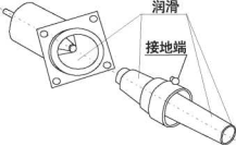
E. Surge arresters
그룹에 번개 피뢰기를 설치해야하는 경우 완전히 절연 된 팔꿈치 유형 산화 아연 피뢰기를 선택할 수 있습니다. 설치하는 동안 그룹 열차는 채택합니다. 이중 패스 케이싱, 이중 패스 케이싱의 한쪽 끝은 팔꿈치 형 플러그에 연결되고 다른 쪽 끝은 번개 피뢰기에 연결됩니다. 서지 체포자 설치 방법:
☆ Connect the grounding wire to the system ground.
☆ Use copper wire to connect the grounding end of the arrester with the system grounding.
☆ Use the contact surface of the lubricated arrester provided by this factory.
☆ 절연 된 작동 레버를 사용하여 차단기의 작동 구멍을 후크하고 차단기를 케이싱 관절에 힘으로 삽입하고 차단기를 제대로 삽입하십시오.참고: 테스트 후 차단기를 제거하고 다시 설치해야 합니다.
F. Fault indicator and voltage display
See Appendix 6
10. Maintenance
A. External maintenance
Regularly inspect all external surfaces of the composition, and repair it immediately if the coating has accidental bruises, scratches and wear.
B. B.. Internal maintenance
그룹의 고압 및 저압 챔버에있는 모든 액세서리 및 장비가 정상적으로 작동하는지 정기적으로 확인하고 각 밀봉 부품에 누출이 있는지 확인하십시오.
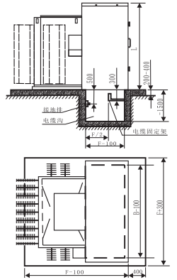
Appendix 1 Combined 변압기 size and installation
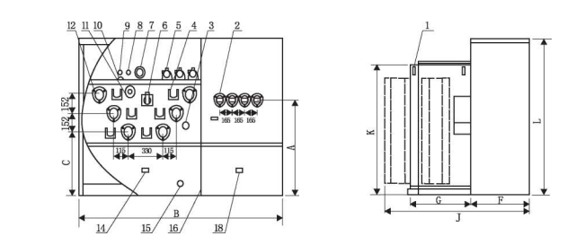
| 1 Hook 11 Oil temperature gauge 2 Low voltage casing 12 High voltage casing socket 3 tap-changer 13 heatsink 4 wall-mounted 14 high-pressure chamber grounding 5 Plug-in fuse 15 Oil drain valve 6 load switches 16 bulkheads 7 Pressure Gauge 17 Fuel Tank 8 Pressure relief valve 18 Grounding of the low pressure chamber 9 Oil injection port 19 High pressure chamber 10 Oil level gauge 20 이름plate |
Figure 1-1 D.imensional diagram of standard ring mesh type and terminal crucian carp combining press
Composition Capacity (kVA). | A | B. B. | C | D. | E | F | G | H | J | K | L |
100 | 1030 | 1971 | 680 | 1091 | 880 | 536 | 560 | 1350 | 1176 | 1346 | 1580 |
125 | 1030 | 1971 | 680 | 1091 | 880 | 536 | 560 | 1350 | 1176 | 1346 | 1580 |
160 | 1030 | 1971 | 680 | 1091 | 880 | 536 | 560 | 1350 | 1176 | 1346 | 1580 |
200 | 1030 | 1971 | 680 | 1091 | 880 | 536 | 560 | 1350 | 1176 | 1346 | 1580 |
250 | 1030 | 1971 | 680 | 1091 | 880 | 536 | 560 | 1350 | 1335 | 1346 | 1580 |
315 | 1030 | 1971 | 680 | 1091 | 880 | 536 | 560 | 1350 | 1335 | 1346 | 1580 |
400 | 1030 | 1971 | 680 | 1091 | 880 | 536 | 560 | 1350 | 1335 | 1346 | 1580 |
500 | 1030 | 1971 | 680 | 1091 | 880 | 536 | 560 | 1350 | 1335 | 1346 | 1580 |
630 | 1290 | 2000 | 796 | 963 | 1037 | 660 | 660 | 1440 | 1540 | 1486 | 1710 |
800 | 1290 | 2000 | 796 | 963 | 1037 | 660 | 660 | 1440 | 1675 | 1486 | 1710 |
1000 | 1290 | 2000 | 796 | 963 | 1037 | 660 | 660 | 1440 | 1765 | 1486 | 1710 |
1250 | 1200 | 2205 | 836 | 1158 | 1047 | 660 | 760 | 1440 | 1865 | 1486 | 1710 |
1600 | 1200 | 2205 | 836 | 1213 | 992 | 660 | 800 | 1700 | 1920 | 1526 | 1710 |
Note: (1). The above dimensions are for reference only;
(2). The terminal type and the ring mesh type have the same overall dimensions.
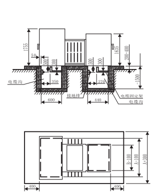
|
|
Figure 1-3 Schematic diagram of the installation of standard combined 변압기 | Figure 1-4 Schematic diagram of the installation of the sub-mother combined 변압기 |
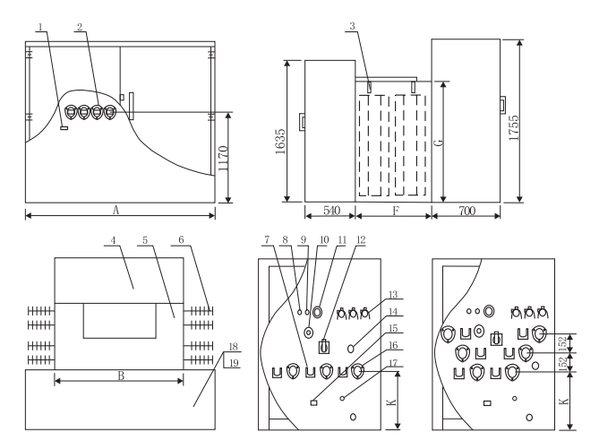
1 Grounding of the low-pressure chamber 2 Low pressure casing 3 Hooks 4 Hyperbaric chamber 5 Fuel tank 6 Heat sink 7 Wall mounting 8 Oil Injection Port 9 Pressure relief valve 10 Oil level gauge | 11 Pressure gauge 12 로드 스위치 13 Plug-in fuse 14 tap-changer 15 Grounding in the hypervoltic chamber 16 High Voltage Casing Socket 17 Spare Nuts 18 Grounding of the low-pressure chamber 19 Nameplates |
변압기 용량 (KVA). | A | B. B. | F | G | K |
100 | 2000 | 1400 | 660 | 1400 | 730 |
125 | 2000 | 1400 | 660 | 1400 | 730 |
160 | 2000 | 1400 | 660 | 1400 | 730 |
200 | 2000 | 1400 | 660 | 1400 | 730 |
250 | 2000 | 1400 | 660 | 1400 | 730 |
315 | 2000 | 1400 | 660 | 1400 | 730 |
400 | 2000 | 1400 | 660 | 1400 | 730 |
500 | 2000 | 1400 | 660 | 1400 | 730 |
630 | 2205 | 1400 | 800 | 1465 | 755 |
800 | 2205 | 1400 | 800 | 1465 | 755 |
1000 | 2205 | 1400 | 800 | 1465 | 755 |
1250 | 2205 | 1400 | 800 | 1465 | 755 |
Note: (1). The above dimensions are for reference only;
(2). The terminal type and the ring mesh type have the same overall dimensions.
Appendix 2 Plug-in fuses
Pull out the fuse tube
1. 압력 해제 밸브를 당기고 연료 탱크의 압력이 완전히 해제 된 후 퓨즈 파이프 작동 구멍을 절연 작동 레버로 연결하십시오.
2.작동 핸들을 아래로 밀어 넣어서 작동 핸들의 이동식 후크가 퓨즈 튜브의 작동 구멍을 잠그고 퓨즈 튜브의 잠금 후크를 90 ° 회전시켜 퓨즈 튜브와 퓨즈 시트 사이의 잠금 상태를 해제합니다.
3. Pull the fuse tube upwards about 100mm, stay for a few seconds, and slowly pull out the fuse tube after the oil on the fuse tube flows.
4. Hold the handle and wipe off the oil stains from the fuse tube.
참고: 오일이 퓨즈 마운트에서 흘러 나오면 압력 해제 밸브를 다시 꺼내서 탱크 내부와 외부의 압력의 균형을 유지해야합니다.
Replace the fuse
1. Loosen the nut of the fused pipe with a wrench and unscrew the other nut with another wrench. (Picture 2-1)
2. Loosen the end bolts and remove the fuse. (Picture 2-2)
(Note: If the fuse is not fused, the flattened funnel-shaped electrode must be straightened before the fuse can be removed)
3. Inspect the inside of the fuse pipe to ensure cleanliness.
4. Insert a new fuse from one end, and the fuse flared electrode is pre-installed at the handle end. (Picture 2-3)
5. Install the fuse pipe and fasten it with a wrench, the torque is about 5.7 - 8N.m.
6.깔때형 전극을 평평하게하고 내부 볼트를 설치하고, 하나의 렌치를 사용하여 용융을 잡고, 다른 렌치를 사용하여 끝 볼트를 조그며, 토크는 약 5. 7 - 8 N. m 이고, 끝 볼트를 풀고, 깔때형 전극이 평평한지 확인하여 좋은 접촉을 보장합니다.
Install plug-in fuses
1. Hook the fuse pipe operation hole with an insulated operating lever.
2. 퓨즈 튜브를 퓨즈 시트에 삽입하고 퓨즈 튜브의 잠금 후크를 90 ° 회전시킨 다음 퓨즈 튜브 시트 사이의 밀봉을 보장하기 위해 잠금 장치를 조입니다.
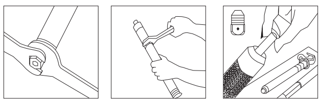
Picture 2-1 | Picture 2-2 | Pictures 2-3 |
Appendix 3 Single-channel sleeve and dual-channel sleeve
D.ouble channel pipe cleaning, lubrication and installation 1.단일 패스 케이싱의 요구 사항에 따라 이중 패스 케이싱과 케이싱 시트의 접촉 표면을 청소하고 그리스를 적용한 다음 래킷이 유휴 상태가 될 때까지 시계 방향으로 이중 패스 케이싱을 나사하여 조임 후 소리를 내십시오. 2. Use a fixing plate to position the double pipe. 3. Use 0. 8mm or equivalent copper wire to connect the grounding hole of the double pipe with the system ground. 4. Install matching parts (such as elbow plugs, lightning arresters or insulation protective caps, etc.). |
|
Single-channel pipe cleaning, lubrication and installation 1. 케이싱과 튜브 시트의 접촉 표면을 청소하고, 그리스를 바르고, 시계 방향으로 단일 패스 케이스에 나사를 바르고, 특수 도구 (7 회 반 회전) 로 조입니다. Note: If the tool is installed with torque, the torque is 13.5N. m. 2. Ground the grounding hole of the single-pass casing with a flexible wire. |
|
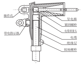
Appendix 4 Elbow plug
|
|
Figure 4-1 | Figure 4-2 |
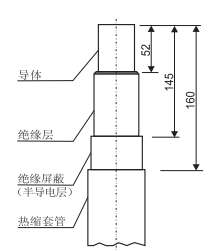
Instructions for installing the elbow plug
1 .Three-core cable split phase treatment
☆ Cut off the inner and outer sheaths at the cable end > 800mm.
☆ Put on branch gloves at the separation phase, heat shrink casing (armor layer grounding) on each single phase wire, see Figure 4-2 for each treatment size.
2 .Elbow plug mounting
☆ 케이블 브러시로 도체 표면을 청소하고, 케이블 도체에 냉압 조인트를 넣고, 연결 도체를 냉압 조인트의 나사 구멍에 나사하고, 나중에 단일 (이중) 케이싱을 통해 삽입합니다.
☆ Choose the appropriate crimping tool, crimping should start from the copper and aluminum connection of the cold crimping joint, and rotate 90° for each pressing, and remove excess lubricant with a soft cloth.
☆ Pull out the connecting conductor and screw it down.
☆ 케이블 표면과 엘보 플러그 내부를 청소하고 윤활을 주며 케이블을 엘보 플러그로 천천히 밀어 넣고 차폐 커넥터로 연결하도록 안내합니다.콜드 프레스 접합의 나사 구멍은 엘보 플러그 끝에서 볼 수 있습니다.
☆ Screw the connecting conductor into the screw hole of the cold pressed joint and tighten it with a mounting wrench until it is torsional 180. (If.)
With other wrenches, the torque is about 12.4N.m) o
☆ Use insulating self-adhesive tape to wrap the elbow plug and the cable heat shrink sleeve.
☆ Use a grounding wire to connect the ground hole of the elbow plug with the system grounding point.
Load input
☆ Sufficient operating distance should be ensured.
☆ Use an insulated operating rod to hook the elbow plug operating hole.
☆ 팔꿈치 플러그의 연결 도체를 슬리브 도체와 정렬하고 연결되어 있다고 느낄 때까지 앞으로 밀어 넣으십시오.
☆ The operation should be fast, accurate, decisive and powerful.
Load cut-off
☆ Hook the elbow plug operation hole with an insulated operating lever.
☆ Turn the insulated operating lever left and right to reduce the friction between the casing surface and the elbow plug.
☆ 팔꿈치 플러그를 빠르고, 정확하고, 결정적으로 강력하게 당겨 근처의 접지선으로 도체를 만지지 않도록주의하십시오.
☆ Hang the elbow plug on the single (double) through connector with an insulated operating lever.
☆ Use the insulation operation lever to cover the insulating protective cap connected to the ground wire on the conductive part.
Notice:팔꿈치 플러그의 작동은 전원 시스템의 안전 및 작동 절차에 익숙한 직원이 수행해야합니다.
Use elbow plugs to separate loads only in emergency (or special) situations, and it is recommended to use a conforming switch.
Elbow plugs cannot be used to close short circuit faults.
Appendix 5 Single (double) pass fittings and insulation protective caps
☆ Single (double) pass connector is used to plug into a live elbow plug, isolate the live cable, segment it, or use it to plug and pull no
The electrified elbow plug plays a role in dust, water and moisture.
☆ The double-way connector can be connected to an elbow-type plug at one end and an elbow-type surge arrester at the other.
☆ Insulation protective caps provide insulation and protective envelopes for sleeves and joints.
Single (double) pass mounting
1. Remove the transportation protective cap, clean and lubricate {refer to the requirements of single (double) through sleeves}.
2. Use copper wire to connect the single (double) through joint grounding hole with the system ground.
3. Hang the single (double) through joint on the wall hanging and tighten the fixing bolt.
4. Seal the corresponding joints with insulation caps.
Note: All relevant components must be in a state of no power before the single (double) pass connector can be installed and removed.
Insulation protective cap installation
1. Clean and lubricate the outer surface of the joint (or casing) related to the inner surface of the insulating protective cap.
2. Connect the grounding wire of the insulation protective cap with the system ground.
3. 보호 캡 잭을 절연 작동 레버로 연결하고 절연 캡을 제자리에 연결할 때까지 관련 조인트 (또는 슬리브) 로 밀어 넣습니다.
Remove the insulating protective cap
1. Hook the protective cap with an insulated operating lever.
2. Turn the protective cap left and right to reduce the friction of the contact surface, and pull it back hard to remove the protective cap.
Appendix 6. Fault indicator and live indicator
The fault indicator is installed on the test point of the elbow plug, 라인이 흐를 때, 장애 표시기의 표시기는 흰색이 있고 자동으로 빨간색으로 전환되어 라인이 현재 "결함" 상태에 있음을 나타냅니다. 회로가 정상으로 돌아 왔을 때, 시스템은 자동으로 표시기 창을 재설정하고 흰색으로 변합니다.고장 표시기에는 두 가지 선택 가능한 임계값, 높은 임계값 및 낮은 임계값이 있으며, 낮은 임계값은 약 400 A (RMS) 이며 높은 임계값은 약 800 A (RMS) 입니다.납품 시 고장 표시기의 표시 창은 고장 표시 (즉,빨간색으로 표시되며, 설치 후, 라인 전압이 5 KV 에 도달하면 몇 분 후에 결함 표시기가 정상적인 작동 상태에 있으며 디스플레이 창은 자동으로 정상 상태로 재설정됩니다 (즉,흰색으로 표시됩니다.)
Note: Only when the line-to-ground voltage of the line reaches more than 5KV, the fault indicator can perform fault display and reset for energy storage.
The live indicator is installed on the test point of the elbow plug, and the continuous flashing of the indicator light indicates that the line is live to alert the line seeker.
Fault Indicators and Live Indicators are fully sealed products for use in a wide range of climates, and their indication status will not change due to vibration or mechanical shock.
Installation steps:
1.표시기의 설치는 두 가지 상황으로 나뉘어 있습니다 : 케이블 헤드가 켜져 있고 켜지지 않으며, 정상적인 상황에서 케이블 헤드는 설치 전에 전원을 끄고 접지해야합니다.
2. Remove the protective cap of the elbow plug test point with an insulated operating lever (the test point should be free of stain and rust).
3. Lubrication indicator mounting the inner surface of the boot.
4.표시기의 작동 구멍을 절연된 작동 레버로 연결하고 표시기를 엘보 플러그 테스트 지점에 놓고 적절한 위치로 회전시킵니다.경고: 테스트 포인트 또는 표시기의 더럽거나 습한 상태 또는 기타 결함이 있으면 라이브 표시기가 라인이 전원이 꺼져 있음을 잘못 나타낼 수 있습니다. at 에서
관련 장비를 작동하기 전에 국가 표준에 의해 승인 된 다른 테스트 방법을 사용하여 라인에 전기가 있는지 확인하십시오.